Flexure Strength
Strain Compatibility
Flexure capacity in Eriksson Beam is calculated using strain compatibility. This is an iterative procedure in which you guess a neutral axis depth, calculate all internal forces and check for static equilibrium. If the section is not in static equilibrium, adjust the neutral axis depth. When performing a strain compatibility analysis, in general two forces are computed, the force in the concrete and the force in your reinforcement. In addition to iteration on the neutral axis depth an additional iteration on the resistance factor may also be required.
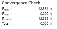
Figure 1: Sample printout of the convergence check
Concrete Force
The force in the concrete is computed based on the area of the concrete above the neutral axis. The force in the concrete in this area can either be computed using a Whitney stress block or by integrating the stress strain curve. The stress strain being used is that presented in Collins and Mitchell’s Prestressed Concrete Structures.
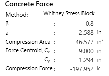
Figure 2: Sample printout of the calculation giving the force in the concrete
Reinforcement Force
The force in reinforcement is computed based on the computed strain in the reinforcement. The strain can be calculated based on the depth of the neutral axis and the assumption that the compressive fiber strain is 0.003. For each reinforcement entity the strain is computed and the stress strain curve is evaluated to get the current stress in the entity. Note that rupture in the reinforcement is not checked and for very deep member or non-standard materials the displayed strain value should be compared against the rupture strain.
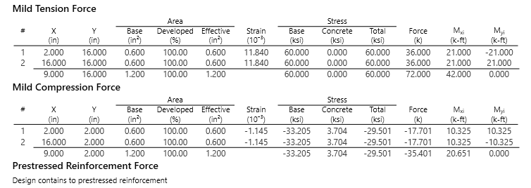
Figure 3: Sample printout of the calculation giving the force in the reinforcement
Moment Capacity
Once the neutral axis depth has been found, the capacity is calculated by computing the moment the above forces generate. By definition, since the section is in static equilibrium, the above forces create a couple moment. Therefore, it does not matter where we sum moments about but for ease, Eriksson Beam sums them about the centroid of the member. With this, the moment about both axis are computed to computed two flexure capacities, or just 1 for a uniaxial problem.
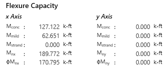
Figure 4: Sample printout of the calculation giving the calculation of the flexure capacity
Biaxial Bending
Biaxial bending can occur whenever biaxial loads are present, the member is asymmetric, or when the reinforcement is not symmetrically relative to the neutral axis. For biaxial bending multiple neutral axis angles can be used, but what is important is to make sure that your demand falls inside the capacity curve of the PM Diagram.
Capacity Contour
For the given location, the capacity contour is created to check flexure capacity. This contour shows how the section behaves biaxially.
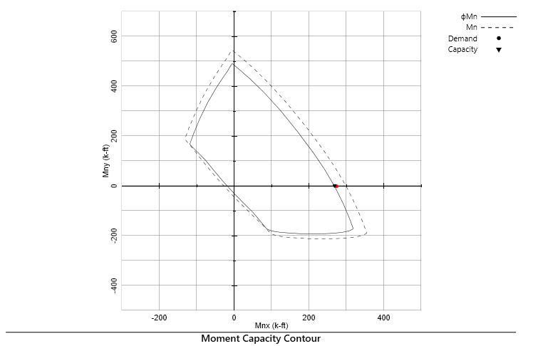
Figure 5: Sample printout of the moment capacity contour
Convergence Criteria
Eriksson Beam iterates on the neutral axis angle until the calculated capacity vector is in the same direction as the externally applied load vector. That is, in the above moment capacity contour diagram, if you drew a line from the origin to the calculated capacity point, it will always pass through the demand point. For symmetric sections, this angle is typically very close to the loading angle. For asymmetric sections, the difference between loading angle and the neutral axis angle can be more noticeable.
Utilization
The utilization, in general terms, is the ratio of the demand to the calculated capacity. For a biaxial / axially loaded member this can be defined in different ways. Because of this, the displayed utilization should only be used as a pass / fail condition and not as a method of determining how much more load a section could carry.