Deflections - Prestressed
Code References
ACI 318-14
Background
In general, four items needed for accurate camber/deflection prediction:
Accurate knowledge of material properties, namely the elasticity of the concrete, preferably on an hourly basis, daily basis is acceptable.
Accurate knowledge of the prestress losses, again preferably on an hourly basis, again daily is acceptable. Note that the use of a time-dependent method for prestress losses is required (not ‘lump sum’).
Changes in loading and support conditions, again at least daily.
System of equations that ties all of this together.
From PCA Notes on ACI 318: “Because of the variability of concrete structural deformations, designers must not place undue reliance on computed estimates of deflections. In most cases, the use of relatively simple procedures for estimating deflections is justified."
Bi-Linear Deflections
Eriksson Beam calculates deflections using the bi-linear method in addition to the deflection multipliers present in the PCI Design Handbook. When using the bi-linear deflection methods, the member allows the user of the gross section properties up until the point the member cracks. At that point the rest of the applied load goes to the cracked section. Because of this, the loads are applied in stages where each stage is checked for cracking. If at any point the member cracks, the stage is split into a pre-crack and post-crack analysis step where their results are combined using superposition. This methodology can be summarized as follows:
Compute Ig for each analysis section.
Compute total moment and total stresses for each loading stage for each analysis section.
Compute deflections for each loading stage at each analysis section, using either Ig, Icr, or a combination of the two. Eci is used for the 1st loading stage, Ec is used for all others.
If an analysis section cracks during a loading stage, (the applied moment exceeds Mcr) compute the point within the loading stage where the section cracks. Then compute Icr for this loading stage and for every loading stage after this one.
For the loading stage where an analysis section cracks, two deflections are calculated. One using the portion of the applied load below cracking in conjunction with Ig, and a second deflection using the portion of the load above cracking in conjunction with Icr, and then sum them.
Multiply the initial and erection stage camber/deflections by the creep and shrinkage multipliers in Table 5.9.2 in the PCI Design Handbook. Note that these multipliers can (and probably should) be reduced based on the ratio of the areas of the mild and prestressed reinforcement present at that analysis section (see the section on the Creep and Shrinkage Multipliers for a detailed discussion of these modifiers).
Sum the deflections obtained at each loading stage to calculate the total deflection.
Loading Stages
Eriksson Beam uses 5 loading stages
Stage | Loads | Material Properties | Section Properties |
|---|---|---|---|
1 | Self Weight + Prestress | Initial | Gross |
2 | Non-Composite DL | Final | Gross |
3 | Topping Weight | Final | Gross |
4 | Composite DL | Final | Composite |
5 | All Others | Final | Composite |
The section properties will change to the cracked section properties if the applied moment exceeds the cracking moment. However, only sections under a positive moment will crack. In example, if Stage 1 cracks along the top of the member from the prestressing, the stage will still use gross section properties at that location.
Cracked Section Analysis
When a given stage cracks, the stage is split into two sub stages, a before cracking stage and a after cracking stage. For these two stages the loads are divided by first computing how much moment can be applied before cracking as follows:
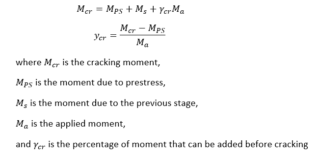
The above procedure is done on a point by point basis. The moment is split by the maximum percentage that is cracked along the member. IE if midspan moment is 20% above Mcr, 20% of all stage loading will be applied to the cracked section.
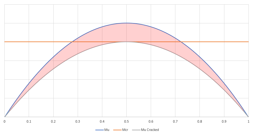
Here, only the red part of the moment curve will be applied to the cracked section
Beam uses a bi-linear deflection approach (Ig/Icr) to calculate deflections at sections where the applied M is greater than Mcr during a loading stage. Only that portion (or %) of M which is greater than Mcr is applied to Icr, while the remainder of M is applied to Ig. In the spirit of ACI E24.2.3.7 when the midspan cracks, the program computes Icr at every section where the member is NOT Class U, using the procedure outlined in Robert Masts’ “Analysis of Cracked Prestressed Concrete Sections: A Practical Approach,”. The program then calculates the % of load that is applied to Icr at the first section that cracks (typically at or near midspan) and applies this % of load to every section where Icr was just calculated.
Creep and Shrinkage Multipliers
For all sections at erection, there are two creep and shrinkage multipliers:
Deflection (downward), applied to the elastic deflection due to the self-weight at release of prestress
Camber (upward), applied to the elastic camber due to the prestress at the time of release of prestress
For non-composite sections at final, there are three additional creep and shrinkage multipliers:
Deflection (downward), applied to the elastic deflection due to the self-weight at release of prestress
Camber (upward), applied to the elastic camber due to prestress at the time of release of prestress
Deflection (downward), applied to the elastic deflection due to superimposed dead load only
For composite sections at final, there are four additional creep and shrinkage multipliers:
Deflection (downward), applied to the elastic deflection due to the self-weight at release of prestress
Camber (upward), applied to the elastic camber due to prestress at the time of release of prestress
Deflection (downward), applied to the elastic deflection due to superimposed dead load only
Deflection (downward), applied to the elastic deflection caused by the composite topping
Condition | Factor | Equation # |
|---|---|---|
Erection: SW Deflection | 1.85 | 1 |
Erection: P/S Camber | 1.80 | 2 |
Final: SW Deflection (non-comp) | 2.70 | 3 |
Final: SD Deflection (non-comp) | 2.45 | 4 |
Final: SW Deflection (non-comp) | 3.00 | 5 |
Final: SW Deflection (comp) | 2.40 | 6 |
Final: P/S Camber (comp) | 2.20 | 7 |
Final: SD Deflection (comp) | 3.00 | 8 |
Final: Topping Deflection (comp) | 2.30 | 9 |
…
In ACI 318-71 9.5.2.3, the base factor used to modify initial deflections to account for long-term effects was calculated using the following equation:
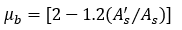
For prestressed construction, this equation reduces to a base factor, μb, equal to 2.0.
In ACI 317-83 9.5.2.5, this equation was changed to:
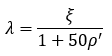
For sustained loads, ξ may be taken equal to 2.0 when the age of the member is greater than 60 months, which matches the base value from the earlier equation (assuming ρ’ = 0). This equation (along with the suggested time-dependent factors) can be seen in Section 24.2.4.1.
The long-term factor applied to the initial deflection caused by the member self-weight for a non-composite member can be calculated as follows:
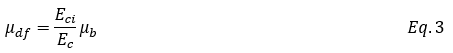
Assuming that the release strength is about 70% percent of the final strength, the initial elasticity would be about 85% of the final. Adding 1 to this (to account for the initial deflection), and you get a factor of 2.70 for this stage. Note that the initial deflection used in these calculations should be based on the final support locations.
The long-term factor applied to the initial camber caused by the prestressing force for a non-composite member can be calculated as follows:
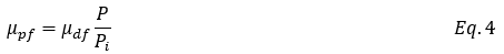
Assuming that the total prestress loss is 20 to 30 percent of the initial force, then the long-term portion of this is about 15% on average (P = 0.85Pi). Again, adding 1 to this value would give us a value of 2.45 for this stage. Note that the initial camber used in these calculations should also be based on the final support locations.
For both non-composite and composite members, the erection modifier for deflection due to self-weight is the same. This equation assumes that about ½ of the long-term effects will have occurred by the time of erection.

Adding 1 to this equation gives us a value of 1.85 for this term. This factor is applied to the initial deflection caused by the member weight.
Similarly, the erection modifier for camber is the same for both non-composite and composite members.
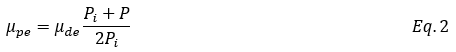
Substituting for the various terms works out to a factor of about 1.80 (rounded up). This factor is applied to the initial camber caused by the prestress at release.
For composite members, the equations for the deflection factors assumes that the section becomes composite at roughly the same time as erection. Therefore, both the self-weight modifier and the camber modifier are adjusted by the ratio of the non-composite to composite moments of inertia. For the self-weight modifier, the new equation looks like this:

For 2” of composite topping, we can assume that the ratio of the moment of inertias is about 0.65. This gives us a value of 2.40 for this factor. This factor is applied to the initial deflection caused by the self-weight of the member.
The equation for the camber modifier is also modified by the ratio of the moments of inertia:

This works out to a factor of 2.20 (rounded down). This factor is applied to the initial camber caused by the prestress at release.
The immediate deflection caused by the placement of the topping is calculated using the non-composite section properties, so the long-term effects must also be modified by the ratio of the moment of inertias:

This works out to a value of 2.30. This factor is applied to the immediate deflection caused by the placement of the topping.
Superimposed dead loads cause immediate deflections and additional long-term deflections. Since the long-term deflection is a result of the creep caused by this sustained load, the long-term deflection factor is assumed equal to the base factor from ACI 318. Note that this factor is the same for both non-composite and composite members.

Adding 1 to this value (to account for the immediate deflection), gives us 3.00 for this factor. This factor is applied to the immediate deflection caused by the superimposed dead load.
Modification to Creep and Shrinkage Multipliers
From Shaikh, A. F., and Branson D. E., 1970, “Non-Tensioned Steel in Prestressed Concrete Beams”, the creep and shrinkage deflection multipliers can be reduced by the addition of mild reinforcement. Using this method, a given multiplier is reduced using the following equation:
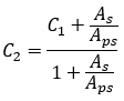
where: C1 = multiplier from Table 5.9.2
C2 = revised multiplier
As = area of non-prestressed reinforcement
Aps = area of prestressed reinforcement
Mild Deflection Multipliers
Mild deflection multipliers are calculated using Eq. 24.2.4.1.1 (shown below). For this method, each load combination computes its’ own reinforcement ratio.
where λ is the deflection multiplier
ξ is the time-dependent factor for sustained loads factor (from Table 24.2.4.1.3), and
ρ’ is the ratio of compression reinforcement to the area of concrete.
This deflection multiplier is applied to all sustained loads on the members.
Hand Calculation
References
Martin, L.D., “A Rational Method for Estimation Camber and Deflection of Precast Prestressed Members,” PCI Journal, V. 22, No. 1, January-February 1977, pp. 100-108.
Mast, Robert F., “Analysis of Cracked Prestressed Concrete Sections: A Practical Approach,” PCI Journal, V. 43, No. 4, July-August 1998, pp. 80-91.
PCI Industry Handbook Committee, PCI Design Handbook, 8th Ed., PCI, Chicago, 2017.
Shaikh, A.F., and Branson, D.E., “Non-Tensioned Steel in Prestressed Concrete Beams,” PCI Journal, V. 15, No. 1, February 1970, pp. 14-36.