Bearing Capacity
Bearing Capacity is calculated for all members based on the PCI Design Handbook, 8th Edition.
Inputs
Input options for all bearing information can be found on the Structural Model tab.
Input Name | Description |
|---|---|
Distance from start / end | The distance from the end of the member to the center line of bearing. This value is also used as s for the plain bearing capacity calculation |
Length | The length of bearing area in the longitudinal direction |
Width | The width of the bearing area in the transverse direction |
Friction Coeff. | The coefficient of friction |
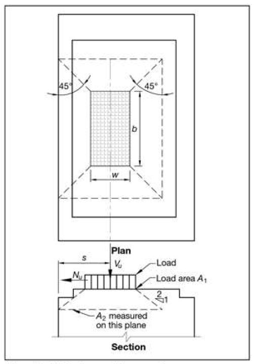
A1 / A2 | The ratio of the bearing areas as defined in PCI 5.5.1. |
Bearing Points | The number of points at each end of the member which support the component. IE for a double T this would be 2. |
Nu / Vu Ratio | The ratio used to calculate Nu and Cr. This ratio is only applied to the sustained load. |
User defined Cr | If the user selected ‘Override Cr’ they can input their own Cr value to use. Note that the Nu / Vu ratio will still be used to compute Nu. |
Plain Bearing Capacity
The plain bearing capacity is calculated based on Ch. 5 Section 5.5.1. When calculating the Cr term, the distance from the start (or end) is used for the s term in Eq. 5-61.
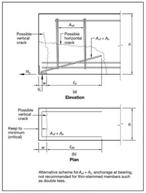
Reinforcement Concrete Bearing
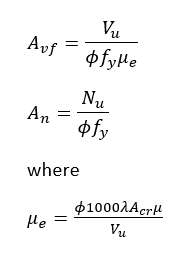
The reinforced concrete bearing is calculated based on Ch. 5 Section 5.5.2. Following 5.5.2, the shear friction equation from Ch. 5 Section 5.3.4 are used. From this, Avf and An are calculated as follows:
In the above equations, Acr is calculated as the sections height times the bearing width.
Applied Reaction
The above calculations refer the Vu throughout the free body diagrams and within the equations themselves. This Vu however, is the applied end reaction at the member, not the maximum shear force coming from the shear diagrams. This is because, per ACI 318-14, The applied load at the ends of the member can, at times, but assumed to go directly into the support, because of this the maximum Vu is less than the end reaction.
Multiple Bearing Points
If your member has multiple bearing points, the bearing geometry should be input as a single bearing pad’s geometry. For example, by doing this, the A1 and Acr values in each equation will be calculated appropriately.